|
LMS Bed Kit and an Extension Modification |
|
|
|
A while back, I promised myself a fall project, the LMS bed
extension kit. For those who do not know, there is a difference of 4
inches in bed length between the HF 7x10 and anybody' else's 7x12. Now
that it's spring, and the shop is livable again, I decided to put the new
bed on. Needless to say, by the time that I decided to do this, LMS
announced that there was a 7x14 bed extension available, which would have
gotten me 2 extra inches of lathe bed. Ah, well. |
|
I've detailed my experiences with the bed kit here, they are
a bit mixed, but overall, a reasonable experience. |
 |
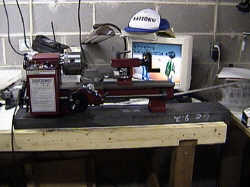
Here's the
sacrificial vict.... OK, here's the lathe as it is
delivered. The chip try is on, of course. |
 |
Here's the box as
you get it. Not really exciting, but then, I haven't unwrapped it yet. |
 |
Here's what you
get. New leadscrew, new bed, new chip tray, new rack, some hardware,
and instructions. |
 |
I removed the old
control box from my lathe, and took a picture to remember how the wires
went. Didn't really need it, but it was a bit comforting. |
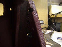
 |
Looks as if the
original manufacturers had their own quality control problems. |
 |
The instructions
tell you how to disassemble the lathe, bit by bit. I took all the
bolts and put them in a compartmented box, along with some of the parts that
fit there. ONE PROBLEM: You see that the two
screws that hold the motor are available, no problem there, but there's two
adjusting screws for the motor belt tension, and the upper one is directly
behind the leadscrew. I had to remove the leadscrew a bit early to get
it out, and when adjusting the motor, I needed to remove the leadscrew. |
 |
Here's another
view. Not a good design, but what can I say? |
 |
In case you ever
wondered what the motor looked like, here it is. |
 |
Even some swarf
gets behind the motor, but not too bad. This is the back of the
headstock part of the lathe. The motor fits in this recess. You
can see the motor belt at the right. |
 |
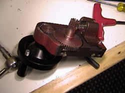
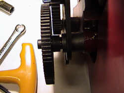
Here's
the end view of the gear assembly. Note that the leadscrew mounting
bracket is flush with the left edge of the bracket. |
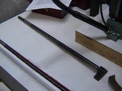 |
Just a view of the
old leadscrew next to the new one. |
 |
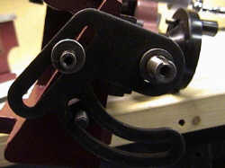
Here's the lathe
apron with the split nut assembly. It's the part that clamps onto the
leadscrew. |
 |
The two beds are
just about the same height, but the old bed is a bit higher. Well, the
new bed can be shimmed up a bit. |
 |
Now if I were going
t omake an extension, where would I want to make the splice?
Obviously, I can't splice them directly. Furthermore, the lack of a
slot under the headstock portion is a bother. I don't remember anybody
milling that out. |
 |
Definitely not
quite an easy decision. |
 |
I thought that I
might be able to make the cut immediately to the left of the support, but I
couldn't see a good reason to do so. I'd have the same difficulty with
the slot, just less of it. I decided to put this one aside and go on
for a bit. |
 |
At least the rack
is spaced properly. I don't think that 0.001 will do much. I
think there's a market for a hemaphrodite digital calipers. |
 |
Here's the rack
mounted. That was actually the best part, in terms of it's easiest and
went the best. Some other things went a bit downhill from there. |
 |
When putting the
carriage back, you are supposed to align it so that it moves freely. I
used the old lathe bed as a weight. |
 |
Guess, what, the
bearings for the leadscrew were not on straight. I put that down to a
slightly off plumb hole. I've always had a difficult time drilling a
perpendicular hole with a hand drill. Probably should have tried
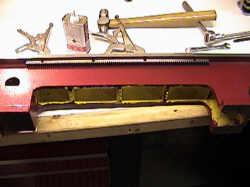
the drill press. Well, I had to mill out the slots for the supports so
I can firstly get them vertical, and secondly, move them slightly left and
right. |
 |
You might be able
to see the slight hole offset, but perhaps not. |
 |
One consequence is
that the holes were a bit closer to the edge than I wanted. You can see that
the pilot hole for the tap is going through the support of the lathe bed.
I checked the original, and it's a bit close, but not quite so close. |
 |
Clamping the
bearings support is a bit tricky, and really really does need a c clamp.
You can't use visegrips, anyway. |
 |
Here's the lathe
bed with the carriage installed, but without the headstock. The
leadscrew is also installed. |
 |
Drilling the banjo
support post had the same problem. While I was careful with the hole,
the drill was not perpendicular. The result is that the gear post is
offset a bit. While I can fix it one way, the other way was to enlarge
the hole for the leadscrew, so it now fits. Another
way is to drill out the hole for the post, and rebuild the post so that it
is threaded internally. That's a project for another day, and I'll
probably get a new banjo. |
 |
It does fit. |
 |
However, the left
support bracket is a bit too far over to the left, which gives very little
clearance to the change gears. |
 |
There's enough,
however. I did try to push out the gears by putting a nylon washer
between the banjo and the gear. That was a bad idea. The nylon
washer washer got trapped between the sleeve and the banjo, and tried to
melt in place.
That causes the lathe geartrain to freeze. Luckily,
it was running at a very low speed and there was no damage. I removed
what was left of the washer.
|
 |
Here's the lathe,
put together, with all the pieces working. |
 |
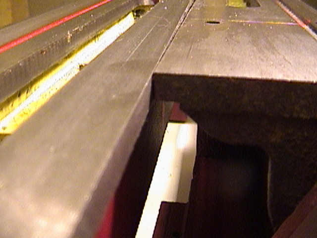
Next, I decided
that since I was on a roll, however mixed it was, I would lengthen the lathe
bed. Finding some documentation from Dave Audette, amongst others, I
started looking at the problem. I can't mill the
edge cleanly, because the mini-mill is a bit small for it. I was kinda
running out of energy, anyway for this. So the easiest way was to cut
very slightly to the left of the first rib. Since I did not want to
try to mill out the lathe bed, the only place to cut it was where you see
the saw cut. I had the same place (MetalSupermarket) cut it as
provided the 6 inch channel for the base. |
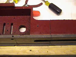 |
Here's another view
of the cut. It took about 2 minutes and 5 dollars, and was worth it,
in terms of sheer aggrivation. |
 |
Mounting the lathe
on the channel was easy enough, I just used the chip tray for the mounting
holes. |
 |
The extra part of
the bed has not been attached. |
 |
I drilled a hole in
both the rib and the end of the old one. I figured that I could leave
a very small gap, and that would be ok. Since the leadscrew is not
extended, the carriage is not going to have to travel over the gap.
The extension is there to park the tailstock when needed,
so it's aligned the best I can align it. |
 |
Aligned, no
tailstock, mounted on the bed, and ready to paint. |
 |
Definitely a rough
joint, but then I knew that. To fix this, I could
remove the paint on both parts, and mill the supports away from the bed by
about 20 or 30 thousandths. Then I mill the end square with the bed.
That allows me to butt the bed together with the end. Shimming the
aluminum pad between lathe ribs and end will allow a good fit, I think.
|
 |
Here it is, ready
to put the final coat of paint on. I've already masked the lathe bed
parts and put on a coat of primer. |
|
OVERALL: A good kit, some of the holes need a bit of
rework. I really need a good method of drilling and tapping very
perpendicular holes. If you do this, take special care with the
perpendicularity of the holes. It makes a real difference. Also
be aware that adjusting the belt on the motor really requires the leadscrew
to be removed.
My procedure was to get it just about right, then tighten
the bolts. Using a screwdriver as a pry bar, I made very slight
adjustments to the motor position until the belt ran in the middle.
Tightening the bolts at that point is not a good idea, so you adjust the
belt tension with the setscrews. That also ends up tightening the main
motor mounting screws as well. |