|
Lathe Tachometer |
|
|
|
This is still in progress, so there’s more
software debugging to be done. The front panel is still under construction |
|
I’m still learning to use the lathe, and one
thing that has made me wonder how to set things up is the speed of the
lathe. Now there is a very recent (came to my notice after I started this
project) lathe tachometer that is available from one of the vendors.
However, I felt that I could roll my own for less cost, and get some
features that were unique.
My design goals were as follows:
1) Tachometer readout from 8 rpm to the lathe’s maximum rpm, 3500.
Moderate size, and based on the 8741 microprocessor, which I have a few
of….
3) SFM readout if the diameter is known, diameter choices are 1/8 inch to
5 inches.
4) Simple photo pickoff from the lathe spindle.
5) expansion capability, perhaps to talk to another controller that can
make the lathe a CNC.
6) Capability to implement the Autostop for the lathe.
|
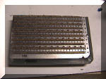 |
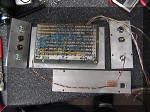
This
is a wirewrap board. They can still be had for very little if you hit the
right hamfest or computerfest at the right time, and the person is selling
them. This is a cut down Augat board that is too thick (1/8 inch) for
standard connectors. It has had the connector fingers cut off, and the board
itself has been cut in half because it’s a small project. |
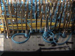 |
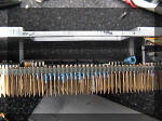
This
is wirewrapping. The wire is 30 gauge silver plated wire with kynar
insulation. Wire is placed in a special tool, which is then placed over the
.025 inch square post. The tool spins the wire around the post, and the wire
pressure welds to the post. It is a gas tight joint and is quite easy to do,
if you have the parts. This wirewrap board has 0.3 inch rows of pins spaced
0.1 inches apart. One plane is power, the other, ground. |
 |
Here’s the case, exploded view, but without wiring. The power regulator is
on the lower panel. The switch panel is to the left, and the connector panel
is to the right. The back and top are left off, because there’s no wiring
here. The board is connected to the front panel, which is a mistake. Wiring
is changed less than the programming. The board now is attached to the back
panel. |
 |
Here’s the bottom,
or top, of the case being drilled. You can see that the braces and angle
plates are used to support the pieces of the case at a proper right angle. |
 |
Match drilling the
top for the countersunk screws. The visegrips are good for holding the side
in place. The front side (to the right) is there only to support the top,
and isn’t attached yet. Why make a spacer when you already have one? |
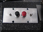 |
The switch plate is
another piece of 1/4 inch aluminum. I wanted this to be rugged. The toggle
switches are for SFM/RPM mode, and latch mode. The two push buttons
increment or decrement the diameter for SFM calculations. |
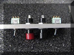 |
Note that the panel
is 1/4 inch thick, and the switches are not made for this. They’re much
happier when connected to a 1/8 inch plate. I had to leave off some little
bits and pieces. |
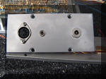 |
The connector panel
has a 5 pin DIN connector to the RPM sensor and the position sensor. The
subminiature phone jack goes to the lathe motor lockout, and the jack on the
right is a metal coaxial power plug jack that takes 12 volts in to run the
whole thing.
|
 |
Here’s the switch
panel during the inspection process. The subminiature phone jack had to be
recessed in the panel. The inspector apparently approved, or perhaps because
nothing was edible, lost interest and left. Nothing negative was said,
however. The power supply regulator is to the right.
|
 |
3/4 inch spacers
mount the board on the front panel. However, making changes to the chip were
a problem, so the spacers were removed and used to hold the board off the
back panel. This leaves 3 holes on the front panel that I’d just as soon not
have. However, the sensor disk and assembly needed to be done next.
|
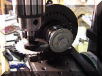 |
The sensor disk is a
piece of .060 aluminum. It is chucked in a 1/2 inch 5C collet in a spin
assembly which gives accurate rotations to 1 degree. This is the second slot
getting machined. The holding fixture is a 1/2 inch bolt. The outside has
already been turned to 2 inches. |
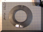 |
The sensor plate.
The inside was bored out on the lathe, with the outside held in the 3 jaw
chuck, reversed. The quick change toolpost was used to hold a standard
boring bar, one of the 1/2 inch cylindrical bars that cost about $20.00 a
set. Works just fine. The bright spot is due to the buffing wheel that was
used to remove the edge burrs from the slitting saw. |
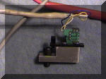 |
The sensor assembly
itself. It came from an old floppy drive, and consists of a phototransistor
and an infrared LED. The small aluminum block was made to mount the assembly
on the lathe. The wire is two conductor shielded, and the heatshrink is the
kind that has two layers. The outer layer contracts, and the inner layer
melts and fills the voids. It’s a waterproof seal and quite strong. |
 |
Here’s a shot of the
IR led in action. This is taken with an infrared camera, so you can see that
the blue and yellow colors of the wire are off.
|
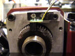 |
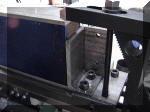
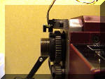
This is the mounting
position of the sensor assembly. The lathe gear assembly was drilled and
tapped for an M6 cap head screw, so all the stuff is designed to be metric
on the lathe. The wires will be routed to the left and down. |
 |
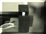
Here's the side view
of the sensor, showing the clearance and the slot in relationship to the
sensor. |
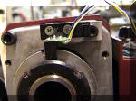 |
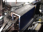
This picture shows
the sensor and the sensor plate. There are two slots, which give one pulse
each 1/2 of a revolution. This works because the tachometer is a period
counter. |
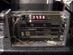 |
The tach working on
the bench. This is part of the self test sequence. The processor is the
large chip on the bottom left. The two lookup proms are immediately below
the display. There are three LEDs to the left of the display to show modes.
The plugins to the board are the I/O connector to the upper left, and the
power connector on a pigtail at the bottom of the box. The board can be
completely removed by unplugging. |
 |
The low range RPM
reads to tenth of an RPM. The lowest range is 8 RPM, and the low range ends
at 99.9 RPM. The high range runs from 100 to 9999 RPM, although resolution
is limited at the higher resolutions, it’s not going up in 1 RPM steps. The
switch between the two ranges is automatic and is just a difference in the
display. |
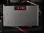 |
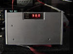
A high range rpm
reading. The front panel is not finished, but the holes are filled with flat
head screws. |
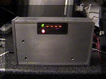 |
The tachometer in
the underrange (stopped) position. This is what happens if the period
counter overflows or the reading would be below 8.0 RPM. The red light is
for the latch mode, and the green light indicates SFM mode. |
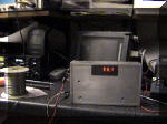 |
The tachometer being
tested. The ham station is in the background for now. |


