A bit of background on this one. I am planning to motorize one of my telescopes. After trying to make some RC motor stuff work (a planetary gear setup, but sadly, all plastic), I decided to try a stepper motor. Well, I do know where to get them, and they are 3.6 degrees/step or 100 steps. One authority suggests that a 50:1 ratio would be good, which would give about 360/5000, or about 0.72 degrees/step. The driving scheme Iím thinking of would be about 18:1 on top of that, so Iíd end up with about 0.004 degrees/step. Thatís 15 arc seconds, roughly, per step.
Now since Iíd need a 50:1 gearbox, Iíd need either a 10 tooth and a 500 tooth gear, or a 20, 40, 20, 50, 20, 50Ö. Forget it! Iíd probably be happier buying one. Also, I donít have the indexing head, quite, for doing gears.

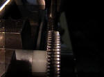
I kept thinking of the shape of the tool, and it came to me that I already had several of them around. Theyíre called taps. Now I know that I would be supporting this at one end only, but I decided to give it a try to see what would happen.
Thereís someone who had a very nice description of how to make gears and how to hob them. Heís much more precise than I, and I give him full credit, Chris Heapy at
http://easyweb.easynet.co.uk/~chrish/worms.htm
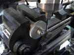
I made a small shaft out of a piece of aluminum, then put a nylon washer on it. The material you see for the gear blank is simply a piece of 1 1/4 inch aluminum rod that was cut to 1/4 inch thick, and had a center hole bored in it.

As you can see, this cuts teeth quite well. Iíd keep the mill at low speed, and brush off chips frequently. The teeth here are probably cut too deep, but it did work. If you look very carefully, youíll see that the cut is a trifle off center. This can be adjusted early on, but I was looking for a proof of concept.

I do recommend that the size of the tap be exactly what you want for the worm drive.
To that end, Iíd suggest threaded rod and cutting down the ends to make the rest of the worm gear. You can always cut your own, but youíd want to be fairly precise with the worm gear diameter. The driven gear is now easy to make. For 20 tpi brass rod, and a 1 inch diameter gear blank, I calculate that youíd get a ratio of roughly 150 to 1. Not bad at all.
I then center bore for the shaft. The shaft end would be faced at this point, too. Without finishing the gear further, Iíd remove it from the lathe and use the power hacksaw to cut it off from the rod, about 1/8 inch over.
Next, Iíd cut the teeth. Then when placing the gear small end in the lathe, Iíd face the large end of the gear to match the shaft and be symmetrical. I have a little room to play with, here.
Iíd probably place the gear in a gearbox milled from 1 by 1 1/2 by 1/2 aluminum, with the motor mounted on a plate at the small end. Of course, thatís just off the top of my head, so the design is up for change. If I had enough small bearings, Iíd put ball bearings at least on the end of the worm gear and at both ends of the driven gear.
Iíd intend for this to be able to support a bit of weight, so the gearbox would have to be rather sturdy. It does support 1/3 (sort of ) of the telescopeís weight when used for azimuth drive. A similar gearbox would drive the elevation system.
Iím not too worried about accuracy, because I intend for this to be in a closed loop servo system.