|
Laser Collimator |
|
|
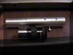
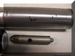
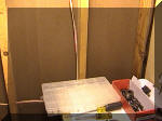
| An
inexpensive laser collimator for aligning a newtonian telescope. Shown here
with a 1.25 inch 25mm eyepiece. |
 |
This collimator uses an
inexpensive laser pointer and allows easy collimation of a newtonian
telescope. There are others who do a much better explanation of telescope
collimation than I, so I’m going to concentrate on the procedure for making
a collimator. In particular, I’m going to do this in exhaustive enough
detail to give a good idea of the design decisions and procedures needed to
make a project of this type. I used a lathe, a mill, a power bandsaw and a
drill press. You can do all this with a lathe and a good drill press. I’d
recommend a cross slide vise for the drill press, it does wonders for
alignment. The materials cost fairly little, the most expensive thing is a
laser pointer. I’d get a good one, the cheap $9.00 ones are workable, but
not really the best.
|
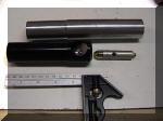 |
This starts out with a piece of
schedule 40 aluminum pipe, a section of 1.25 inch aluminum rod, and a laser
pointer. You’ll need some 10-32 stainless steel setscrews and a 10-32 cap
head screw.
Schedule 40 aluminum pipe has about a 1 3/8 outside and about 1 inch
inside diameters. There was no sense in trying to bore out a 1 inch hole in
the outside piece. Might as well pay a little more and have it done for me.
The inside piece will hold the laser pointer and will be cut at a 45 degree
angle for the mirror. Another piece of the 1.25 inch rod is used for an end
plug. In the photo to the left, the 1.25 inch outside diameter has been cut,
which is the eyepiece diameter. The outside has been turned down just enough
to make the outside concentric with the 1.25 inch part. The inside part has
been turned down to 1.042 inches, the ID of the schedule 40 pipe.
|
 |
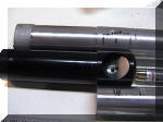
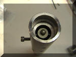
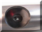
This is the orion collimator
that this design is based on. You can see the mirror through the hole, and a
small setscrew that locks it in place. The outside is one piece of aluminum,
the inside another. |
 |
Let’s look at the pointer end
and the outside first. You can see that the mirror end fits up to the joint
at the large to small section. There’s a 1 inch space left for the mirror,
and a 1/4 inch safety gap beyond that. Next, the laser pointer is sketched
in place, and the switch location is marked. You can see that the end of the
large section is still not machined, and will be cut off later. So, for that
matter, is the end of the inside section. |
 |
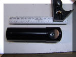
A
closer view of the outside end. The mark at the end shows where the plug for
the end would go. No rocket science here. The first operation is to turn
down the pipe. One end is turned down to 1.25 inches, that’s the eyepiece
diameter. It is long enough to match the end of the collimator. In the next
few pictures, the two non-machined ends will be cut off with a bandsaw. The
ends are then faced, very gently, in the lathe. The power bandsaw is not
absolutely needed, you can make a decent cutoff with a good hacksaw, but a
good idea would be the kind of hacksaw that has a frame included, this would
allow you to make an even cut. It’ll be a bit of a job, though. This shows
the outside after the ends are cut and faced. It’s just a hollow tube so
far. |
|
|
 |
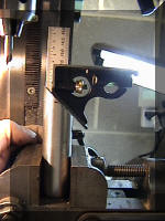
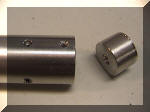
Here’s a view of the layout
before cutting. It shows the cut down end of the outside, and the relative
view of the inside in the proper position.
|
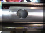 |
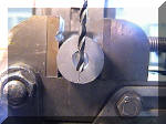
This is
about a 3/4 inch hole or so. It is the hole for the mirror. There’s a small
dimple that marks the bottom of the hole, but it isn’t needed. If you get
the alignment of the lock just exactly right, the lock and the hole will
line up. If I had put the center section in just after I had drilled the
mirror hole, then had drilled the lock pin hole, I would have had an exact
alignment.
Didn’t think of that, though. You can see how the center section is
supposed to fit. The center of the mirror was marked before the section was
put in, and extends a bit beyond the mirror hole.
|
 |
 |
The width of the laser pointer
is a bit bigger than 1/2 inch. So the hole drilled for the laser pointer is
3/4 inch wide. Looking at what the lathe will do, I decided not to try to
bore out the hole. I was rather nervous about that much metal unsupported
and I don’t have the proper follower or the steady rest. So I ran out to the
local hardware store, and $20.50 later, I had a 3/4 inch drill with a 1/2
inch shank. On to the drill press. |
 |
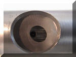
The smaller end was drilled to
3/8 inch. That’s about the same size as the one in the orion collimator.
That was also drilled in the drill press. I had not so much problem drilling
the hole, but the lathe bed was too short for the drill and tailstock! Since
this doesn’t have to be exact, the drill press would do. |
 |
Aligning the tap drill in the
mill for the retainer screw. You’ll see it later. It’s within the 1 inch
length of the mirror. I used a 10-32 by 1/4 setscrew and that needed a #21
drill. A set of number drills is a nice thing to have. |
 |
Tapping the lock screw. This
screw locks the inside in place, even if there are no other screws to help.
The screw presses against the inside wall of the outside section to lock the
inside. I’m using the upper section of the hole (which will be removed) to
guide the tap. I had to drill it out, since the original hole was the #21
for the tap. I use tap-free, and that has helped the tapping enormously. |
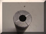 |
Cross hairs scribed on the front
end of the insert. This was a good idea, except that when the mirror section
is cut off (45 degrees with the bandsaw), you lose the scribe marks.
|
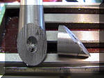 |
The mirror as cut. I don’t have
a use for the lower section yet, but it’s a nice 45 degree cut that might be
useful in another project. Now the mirror has to be cleaned up a bit. |
 |
The mirror section is aligned
two ways. First, it has to be rotationally aligned so the plane of the cut
is square with the table. The square’s 45 degree part works well.
|
 |
Next, the press vise is tilted
45 degrees. I used the flats of the end mill to align the mirror cutoff flat
to the mill. You can tolerate a bit of misalignment here, and the 45 degrees
is not sacred. All you’re looking to do is to smooth out the saw cuts. If
you don’t have a mill, then improvise a 45 degree holder and use fine
sandpaper. I’d use about 120 grit, then 400 grit.
To smooth the edge of the mirror, I used 400 grit sandpaper just to take
the very sharp edge off.
Similarly, I used a file in the lathe to round the edges on the inside
and outside pieces. The inside holes can be smoothed with a deburring tool.
|
 |
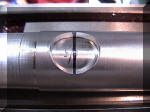
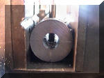
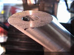
This is a shot of the mirror
when polished. I left a few tool marks in it, mostly because it really
doesn’t matter too much. What you want is a sanded surface that will diffuse
the laser light. This keeps you from getting hit with a laser beam, and
makes the beam visible from more angles. This is where the mirror sits in
the holder. The lock screw is visible at the bottom of the hole.
|
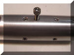
The view above is the switch (cap head ) screw and the
alignment screws. The back 4 are generally fixed. |
To drill the alignment holes. I
used the lathe to get a parallel by moving the lathe carriage. By rotating
the lathe chuck 90 degrees, I get the quadrature needed for the alignment.
Drill the holes, when aligned, completely through the body with the center
section in place. The initial countersink should not be too deep, since the
outer section is relatively thin. I tapped the holes completely through to
the center, through both inside and outside pieces. The switch hole doesn’t
go all the way through.
Next, I removed the center section and countersunk all the holes. I also
drilled out the alignment screw holes to fit the whole screw width. Only the
center section will hold the alignment screws.
|
|
 |
| You can see the alignment screws
just a bit in this view. The keychain attachment point protrudes a bit
beyond the inner part. I decided to put a plug in the back to close up the
whole assembly. I made it from the same 1.25 inch bar stock and turned it
down to 1.040 inches as before. I used the countersink hole for the live
center to clear the key fob attachment.
|
 |
There’s a very small groove that
runs around the outside of the plug. It’s meant to allow fingernails or some
sort of small screwdriver to get a pry point when the plug is getting
removed. There’s one 4-40 flathead phillips screw holding the plug in. There
doesn’t need to be more, because the plug has no stress on it. |
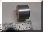 |
A shot of the plug by itself. It
protrudes just a little so it can get grabbed and pulled out. It butts up
against the inside piece. |
 |
I used the lathe to help align
the laser. The back screws are adjusted to center the pointer visually. As
you rotate the lathe by hand, you will see the spot wobble. Pick the visual
center and align first one, then the other axis. You’ll have to loosen one
side to adjust the other, of course. |
 |
Look in the center of the 2 x 4,
there’s a small red spot. That’s the laser pointer. The center bore of the
lathe headstock makes a very good optical tunnel.
|
 |
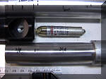
In use, the laser beam is
reflected back and bounces off the mirror. The spot will vanish when the
beam is properly aligned, which, after all, is the end point of this
exercise.
|
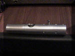 |
Another view of the laser
collimator. Tighten the screw until the pointer turns on, loosen it until
the pointer turns off. Simple enough. |
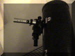 |
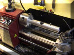
Collimator in position on an 8
inch newtonian. Behind the collimator and focuser is a 5 x 50 mm finder.
Tighten it in place before use, otherwise it will wobble and will not assume
the position of an eyepiece in the scope. |
| This
was a nice project. It made me aware of the limitations of the lathe, but
with the equipment I was able to throw at it, everything went quite well. An
indexing and dividing head would have been a nice idea, especially for
drilling holes in quadrature, but there are ways of working around it. The
collimator is worth at least $70.00, and all it cost me was about $8.00 of
aluminum, a $10 laser pointer, and about a thousand dollars worth of machine
shop equipment. Quite a bargain…. |


