|
Astronomy: A Barn Door Mount |
|
|
|
This is an
early project, made without some of the sophistication that I can bring to
the later projects. You can make this with some relatively simple
woodworking tools, and parts from a floppy disk drive. The older the
drive, the better. |
|
I'm
regernerating the text from memory, so this will not be as detailed as most,
hopefully, the pictures will speak for themselves. The critical
dimensions are the hinge to the major arm pivot, and the secondary arm
distance to the pivot and length. |
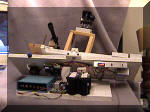 |
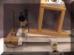
Here's the overall
project. The blue box is the stepper motor controller, there's some
old (and removed) gell cell batteries, and the driver for the stepper motor
is the same floppy board that was in the drive. Even the sensors came
from the drive. This all came from a 5 1/4 inch floppy.
|
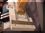 |
I used a piano hinge
to make the whole thing sturdy. The aluminum angle is used to give the
bearings a smooth place on which to ride. |
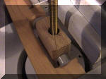 |
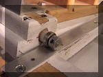
The stepper is mounted
below (details later) and the drive screw (1/4 x 20) goes up through the
piece of oak. The bearings on the drive allow the nut block to pivot
freely. There's a threading insert in the oak that the brass screw
rides in. |
 |
The sight scope (for
Polaris) is mounted on a rather kludged together mount that still works
well. Again, most of this can be done with standard woodworking
tools.... Some degree of neatness beyond this is recommended. |
 |
The inner platform
rides on bearing wheels made from more floppy drive bearings. This
moves smoothly, and if the stepper screw is wobbling, there will be less
motion transmitted to the camera. With a good machine shop, you
wouldn't have this problem, but the setup actually works around this. |
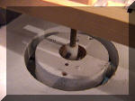 |
Using a hole saw
twice, you make a round section. It's pivoted the same way the nut is
pivoted, so that the stepper motor (mounted below) can maintain a true
tangent arm angle to the main arm. |
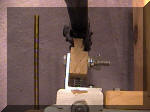 |
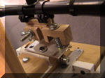
Detail of the scope
mount. It'll pivot up and down (use a spring for the up and down part)
and slotting it does left and right. |
|
|
You can see the spring
for the up and down. The slot allows the whole bracket to pivot left
and right, which gets you the coarse centering. The crosshair adjust
on the scope will take care of the fine adjustments. |
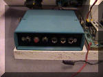 |
Inside this box
there's an 8741 microprocessor (very old), it homes the arm (you use the
home sensor and a little piece of brass), and runs up about an inch, then
starts going slow. You can select slow up, home, and fast up.
Next to the controller is a surplus lead-acid battery charger. It'll
want 18 volts or so (12 volts AC) to charge the battery. |
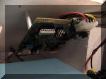 |
The original drive
board is used for controlling the sensors and the stepper. Since the
controller is wirewrap, there were no printed circuit boards needed for this
project. Replace the terminating resistor from the drive with a 2.2K
or 4.7K resistor pack. |
 |
In the foreground is
the little brass flag that tells the processor that "home" has been reached.
You'll have to reverse two of the wires to one of the stepper coils to get
the motor to reverse itself. This is because the little controller on
the stepper drive board has enough smarts to obey a "home" command.
The drive worked in the opposite direction, so flipping one will fix
that. |
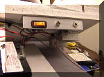 |
A small piece of
aluminum bracket holds the power switch, pilot, and the power input.
It's polarity protected, so no problems here. |
|
A trifle
rough in construction, this is still good for 5 minute plus exposures.
There's too much light pollution here to try for much more, and you're
limited to the size lens you can put on the camera. The more telephoto
the lens, the more critical the arm is.
To align this, you point the axis at a fixed point in the distance.
Move the arm up and down and adjust the scope mount so that the center
(crosshairs) point does not move. More is contained in the other sites
that talk about scotch arm (barn door) mounts. This is more of a
construction project. |


